

Login
Purchase products from our website and enjoy Free Shipping.

Poduct Detail
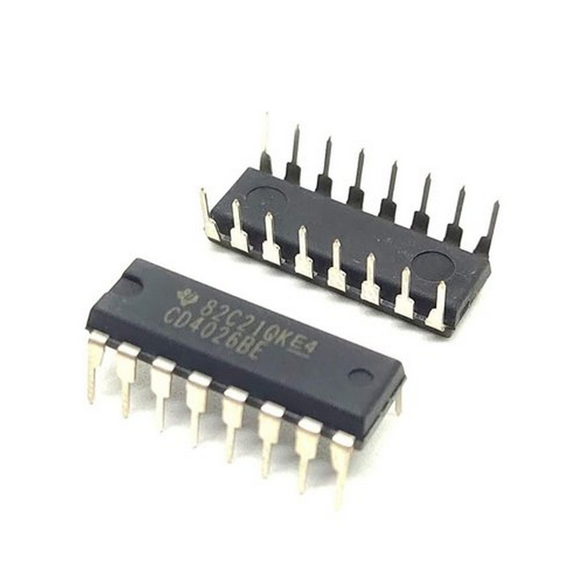
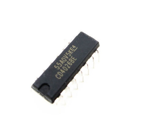
CD4026 Johnson Decade Counter/Divider With Decoded 7-Segment Display IC in Pakistan
KHREED.PK
Rs. 0
In StockSKU:
Categories & Tags: Computers & Laptops, Computer Components, Imported, Pakistan, Discount, High Quality
Share:
Features:
-
Counter for 7-Segment display
-
Can drive a common cathode 7-Segment display directly
-
Easy to interface with timer or micron rollers (TTL compatible)
-
Can be easily cascaded with more IC to display higher range of number
-
Maximum Clock Frequency: 6Mhz
-
Available in 16-pin PDIP, GDIP, PDSO packages
-
Note: Complete Technical Details can be found at the CD4026 datasheet given at the end of this page.
Description:
CD4026 Pin Configuration:
Pin Number | Pin Name | Description |
1 | Clock (CLK) | The counting happens when this clock pulse goes high , this pin is normally connected to 555 timer or other uC to produce a pulse |
2 | Clock Inhibit (INH) | Connected to the Ground (low) of the circuit, to enable clock pin |
3 | Enable Input (DEI) | This pin is connect to +5V (high) to enable the output pins (Out A to Out G) |
4 | Enable Output (DEO) | This is an output which always stays high, this pin will be only if more than one CD4026 IC is used (cascaded) |
5 | Divide by 10 (CO) | This is the carry over output pin; it produces a pulse after counting till 9. This pin will be only if more than one CD4026 IC is used (cascaded) |
6,7,9,10,11,12,13 | Out A,B,C,D,E, F,G | These are the decoded output pins which should connected to 7-Segment display. |
8 | Ground | The ground pin should be connected to ground of circuit |
14 | Not 2 out (UCS) | This is Ungated C segment pin. This is an output pin which will be rarely used when division is required. |
15 | Reset | This input pin when made high (+5V) will reset the count to 0. |
16 | Vcc | This pin powers the IC, typically +5V is used. |

CONTACT INFORMATION
CALL
+92 318 04500 11
FIND US
Lahore Pakistan
Info@Khreed.pk
sales@Khreed.pk